

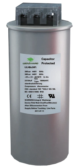
Low-voltage Power Capacitors
ULHBC series self-healing, environmentally friendly, explosion-proof low-voltage power capacitors are composed of a one-piece molded aluminum shell, high-quality polypropylene film, and high-strength terminals. The capacitors feature a high-stress conductive layer, capable of withstanding surges and high-temperature operating environments.
Product Features
· ULHBc selects different reactance rates according to load characteristics, effectively suppressing 5th and 7th harmonic amplification and ensuring the safety of capacitor branches;
· Phase-by-phase switching adapts to three-phase unbalanced reactive power requirements;
· Cylindrical capacitors with a self-healing explosion-proof design;
· Reactors utilize foil winding technology for excellent heat dissipation;
· Compact structure, easy maintenance, suitable for space-constrained distribution rooms;
· Equipped with overvoltage and overtemperature protection functions to ensure long-term stable operation.
Products Description
ULHBC series self-healing, environmentally friendly, explosion-proof low-voltage power capacitors are composed of a one-piece molded aluminum shell, high-quality polypropylene film, and high-strength terminals. The capacitors feature a high-stress conductive layer, capable of withstanding surges and high-temperature operating environments.

Data Sheet
| Low-voltage capacitors | |
| Technical Standards | IEC831-(2)IEC60831-12VDE0660-46+47GB12477-91 |
| Rated Voltage | 280V,300V,450V,480V,525V,750V |
| Rated Capacity | 5kvar,10kvar,15kvar,20kvar,25kvar,30kvar,40kvar |
| Rated Frequency | 50Hz/60Hz |
| Overvoltage | 1.1Un 8 hours/day 1.15Un 30 minutes/day 1.3Un 10 minutes/day |
| Maximum Instantaneous Overload Current | 4In |
| Capacitance Deviation | ±3.5% |
| Maximum Inrush Current | Maximum 200In |
| Dielectric Loss | ≤0.11W/Kvar |
| Inter-electrode Withstand Voltage | 2.15Un, 2s (Factory Test) 2.15Un, 10s (Type Test) |
| Ambient Temperature | -40℃~+55℃ |
| Normal Environmental Service Life | ≥200,000 hours |
| Cooling | Natural or forced cooling |
| Installation Location | Installation within the cabinet must be below the reactor |
| Altitude | ≤4000m |
| Solvent | High-grade polypropylene film |
| Discharge Resistance | 180s discharge to 75V, 60s discharge to 50V |
| Sealing Test | No leakage at 75℃ (qualified) |
| Over-Temperature Operation Test | No abnormalities after 120 minutes of rated operation at 105℃ |
Q&A
Q: 1.What are the main functions of low-voltage capacitors?
A: The core function of low-voltage capacitors is reactive power compensation (power factor correction), specifically bringing the following benefits:
(1)Improved power factor, avoiding electricity bill penalties: Raising the power factor to above 0.95 meets the power supply department's assessment requirements, avoiding power factor penalties due to excessively low power factors.
(2)Reduced line losses: After reducing reactive current, the active power loss (I²R) of the line is significantly reduced, with actual measurements showing a reduction of 20%~40% in line losses.
(3)Released transformer and line capacity: Under the same active load, the apparent power is reduced, releasing the load-carrying capacity of transformers and cables, delaying capacity expansion investment.
(4)Improved voltage quality: Reduced line voltage drop, stabilized terminal voltage, and improved the operating efficiency of electrical equipment.
Q: 2.What are the precautions for installing low-voltage capacitors?
A: (1)Ambient Temperature: The operating ambient temperature for capacitors is generally -25℃ to +55℃ (refer to the product nameplate for specific details). They should be installed in a well-ventilated cabinet, avoiding direct sunlight and proximity to heat sources.
(2)Installation Spacing: Sufficient heat dissipation spacing should be maintained between capacitors (recommended ≥25mm). When arranging capacitors on different levels within the cabinet, hot air convection should be considered.
(3)Vertical Installation: Cylindrical capacitors should be installed vertically (terminals facing upwards) to avoid uneven distribution of internal insulating oil due to tilting.
(4)Discharge Device: Ensure the built-in discharge resistor of the capacitor is intact, or use an external discharge device to ensure that the residual voltage drops below 50V within 1 minute after power failure.
(5)Grounding: The capacitor casing and cabinet should be reliably grounded.
(6)Keep Away from Harmonic Sources: The compensation cabinet should be kept as far away as possible from high-power frequency converters, rectifiers, and other harmonic sources, or a reactor should be installed on the incoming line side.
Hot Tags: low-voltage power capacitors, China low-voltage power capacitors manufacturers, suppliers, factory


Send Inquiry
